Ito Resistance Vs Temperature
When resistance FALLS with an increase in temperature the material is said to have a NEGATIVE TEMPERATURE COEFFICIENT. Greek symbol α represents temperature coefficient of the material.

Effective Resistivity And Sheet Resistance Of Igzo Ito Multilayer Films Download Scientific Diagram
100 ohm Platinum RTD Fahrenheit Temp Resis Temp Resis Temp Resis Temp Resis Temp Resis-40 8427 19 9718 78 10995 137 12260 196 13513.

Ito resistance vs temperature. The resistivity is also known as specific resistance. The resistance of the material depends on their temperature. The entire surface of the glass substrate is coated with the ITO film but only the center portion of the substrate 30 mm in diameter is certified.
The equation below is used to find the resistance of object at any temperature when the resistance at some specific temperature is known. Changes in microstructure and electrical properties of ITO films according to. Feb 24 2012 During increasing of temperature if we take its resistance at a regular interval we will find that electrical resistance of the metal piece is gradually increased with increase in temperature.
Resistivity of FTO coated glass substrate is constant up to 600 0 C. In some cases films deposited at low substrate temperatures can be annealed at higher temperature to achieve lower resistivity. ITO glass slides usability is suitable for inverted work.
In a material where the resistance INCREASES with an increase in temperature the material is said to have a POSITIVE TEMPERATURE COEFFICIENT. It depends on the material of the wire. Resistance Vs temperature graph we will get a straight line as shown in the figure below.
2a represents the transfer length as a function of ρ c ρ cslThe measured values for ρ c ρ csl for two different types of ohmic contacts with and without the Ni 5 nmAu 5 nm stack provide transfer lengths of 114 and 456 μm. FTO coated glass slides is rarely used for inverted work. T a is the annealing temperature.
2 Sensor Type 1. The TCR is the slope of a chord joining two points of temperature on the ΔRR fT curve. Temperature coefficient of resistivity ρρ o 1αTT o RR o 1αTT o ρ T 0 reference temperature α temperature coefficient of resistivity units of C-1 For Ag Cu Au Al W Fe Pt Pb.
Apr 17 2018 Technically the rate of change of resistance is measured in terms of the temperature coefficient of the material. The resistance of the wire increases with the length of the conductor. 7ƒ Thus one would expect an inverse relationship between the sheet resistance and the grain size of the thin film.
AFor some unknown reasons the temperature behavior of resistance for the A1 film could. Nov 01 2017 Results of transfer length calculations for resistivities and thicknesses used in this work for the current spreading layer are shown in Fig. Deposition was carried out with RF magnetron sputtering method and the substrate temperature was held at 70 C in lack of the thermal damage to the polymer substrate.
If this straight line is extended behind the resistance axis it will cut the temperature axis at some temperature t 0 o C. Values of α are 3-510-3 C-1 T slope α. If we plot the resistance variation with temperature ie.
Aug 08 2013 Abstract. Temperature function ΔRR fT of precision resistors is commonly represented in the industry by the value of the temperature coefficient of resistance TCR. It is inversely proportional to the cross section area of the conductor.
Tering mechanism then the sheet resistance Rs can be expressed as Rs 1nqmgt 1Md 6ƒ where M nq2t 2pm nkT 12 exp 2fbkT. From the graph it is. R2 R1 1 α1 T2 - T1.
The relative resistance change vs. Resistance of ITO glass substrate increases with temperature. Nov 15 2006 Indium tin oxide ITO films with various thicknesses in range of 40280 nm were prepared onto a plastic substrate PMMA.
Table 1 Values of relevant parameters for ITO thin films. Indium-tin oxide ITO films have been traditionally deposited at elevated substrate temperature of 400C to achieve low resistivity and high transmission. ITO Sheet Resistance Standards ITOSRS Product Description The ITO Sheet Resistance Standard consists of a glass substrate with a thin film of indium tin oxide sputtered on it.
The temperature behavior of resistivity of a normal metal is given by the BlochGrneisen BG law 17 ρ ρ 0 βT T θ D 4 θ D T 0 x5dx exx. A plot of sheet resistance of ITO thin films versus grain size is shown in Fig. Two such temperature points indicate the temperature range.

Low Resistance Highly Transparent And Thermally Stable Ti Ito Ohmic Contacts To N Gan Journal Of Vacuum Science Technology B Microelectronics And Nanometer Structures Processing Measurement And Phenomena Vol 27 No 3

Pdf Thickness Dependence Of Resistivity And Optical Reflectance Of Ito Films

Low Resistance Highly Transparent And Thermally Stable Ti Ito Ohmic Contacts To N Gan Journal Of Vacuum Science Technology B Microelectronics And Nanometer Structures Processing Measurement And Phenomena Vol 27 No 3
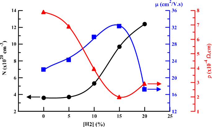
Electrical Conductivity Enhancement Of Indium Tin Oxide Ito Thin Films Reactively Sputtered In A Hydrogen Plasma Springerlink
Https Iopscience Iop Org Article 10 1149 1945 7111 Ab64bd Pdf


Komentar
Posting Komentar